
Robotics & Engineering - Week of 12/16/24
During my time in the Robotics Shop 5th and 6th period this week, I made significant headway on the lightbox project. For my lightbox, I will be making a transparent “EXIT” sign that you frequently see in modern office buildings. These signs are very expensive and can be found online for hundreds of dollars. My plan is to make it for much less. The most expensive component to the project would be the acrylic, which can be found for about 10 dollars for an appropriate size. On top of this, the existing exit signs tend to not have any special features, so mine will have a disco strobe party mode!
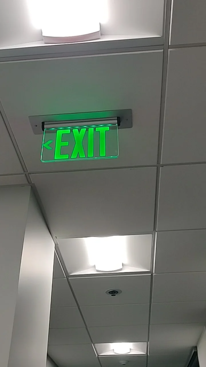
The lightbox project is a mandatory project for all sophomores. The challenges it presents are a great way to teach PCB design, manufacturing, designing, and coding all at once. The learning process is taught by doing, which I find very effective. In the end, the lightbox should be a standalone box with a piece of acrylic secured to the top. The NeoPixel LEDs will illuminate the acrylic piece, highlighting the laser-engraved image on it. My design goes against the typical design format, where the box is normally larger than the acrylic. In my case, I am using a 7x10 inch piece of acrylic for maximum visability. At the same time, the box itself is designed with the lowest profile in mind.

I successfully prototyped a working version on a breadboard. It utilized a ATTINY84 microcontroller with a string of NeoPixels. Using a custom written c++ NeoPixel library running on the microcontroller, I was able to control them identically to how the Adafruit NeoPixel library could, just with less bloat. (The ATTINY84 has such little storage the library doesn’t fit on the board completely.)
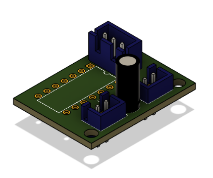
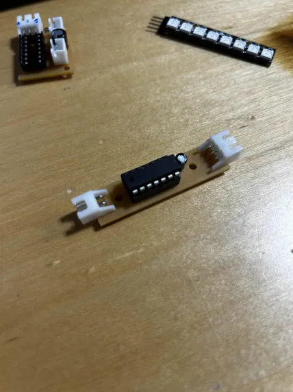
The board shown (above) was my first version as an attempt to make a compact PCB for the controller and the electronics, but I ended up redesigning it to make it more compact with fewer components and traces. The new board will be a long and skinny design allowing it to fit into the narrow footprint of the exit sign’s box.

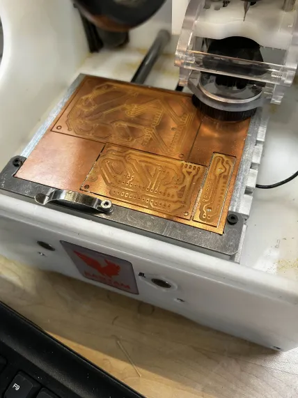
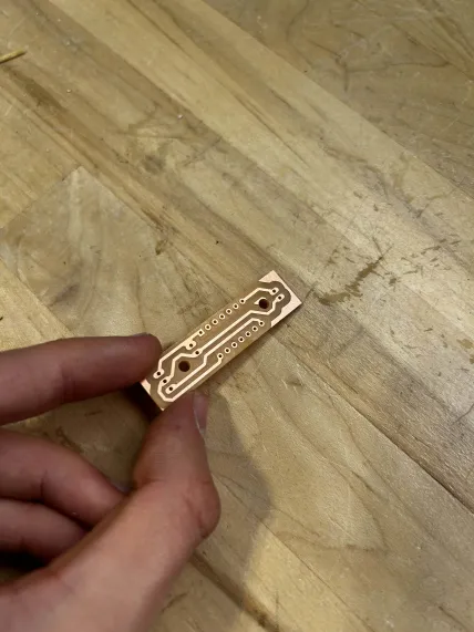
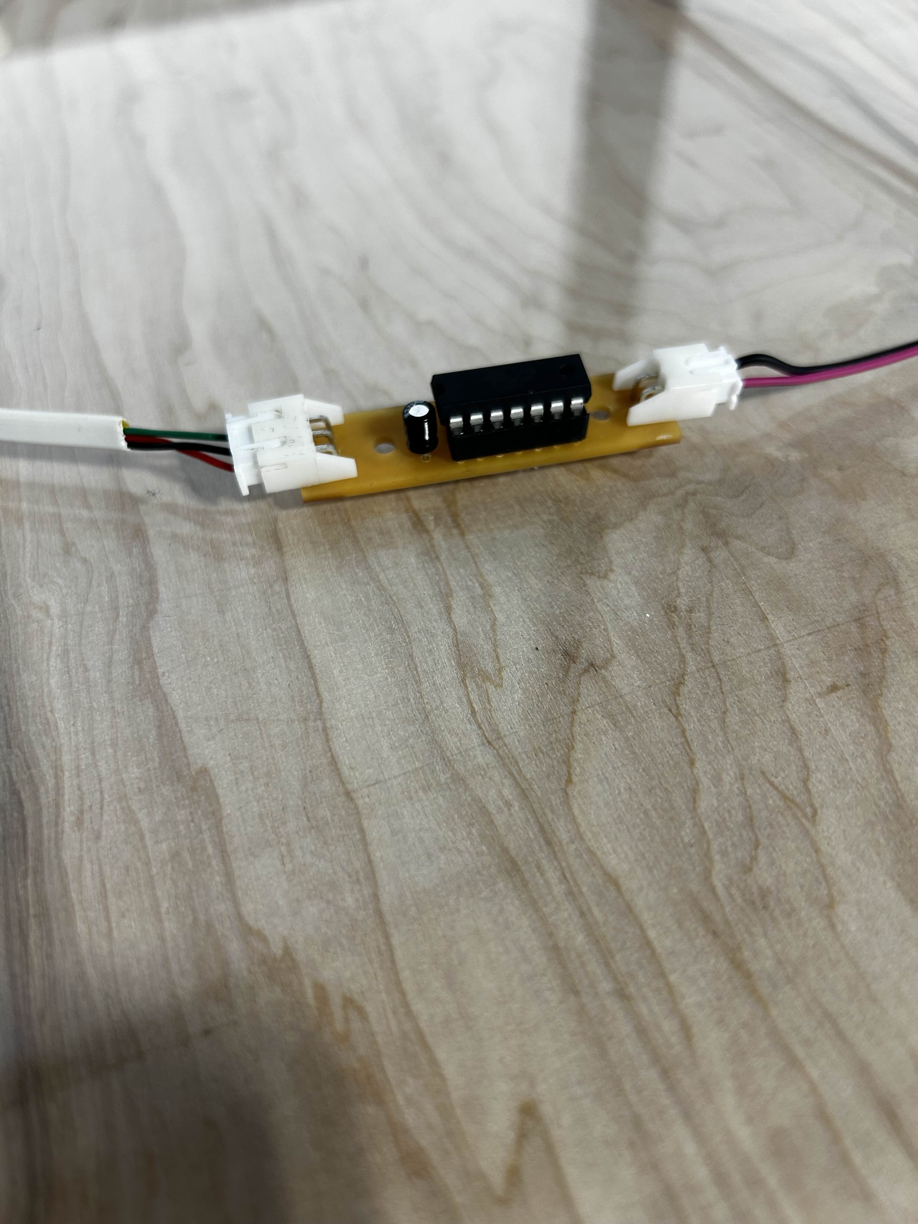
With the new board designed, I milled it on our PCB mills and began to solder it together as per the schematic I created. From there, I crimped some wires for the JST connectors. There are only 2 connectors on my new board. One is dedicated for the button (the input for the lightbox) and the other one has 3 pins- 5V, GND, and SIG for the NeoPixel and also for powering it from a 5v power source.
0
Views
